Altair OptiStruct Topology Optimization: Workflow & Tips
Master Altair OptiStruct topology optimization to cut structural weight by 40%. Learn to set constraints, interpret results, and refine your geometry.
Altair OptiStruct Topology Optimization: Workflow & Tips
Altair OptiStruct topology optimization lets engineers strip a structure down to its most efficient material layout by removing everything that isn't carrying load. Instead of starting with a shape and checking if it works, you define loads, constraints, and a design space, then let the solver figure out where material actually needs to be. The result is often an organic-looking geometry that outperforms anything you'd sketch by hand, using less material without sacrificing structural performance.
At Arched, we apply a similar philosophy to bridge engineering. Our generative design engine runs thousands of physics-driven iterations to find optimal configurations for beams, spans, and piers, scored across cost, durability, carbon impact, and code compliance. Where OptiStruct operates at the component and assembly level across industries, our platform focuses specifically on bridge plan sets, automating the trade-offs that structural engineers and contractors typically grind through manually. Both approaches share a core principle: simulation-driven exploration beats manual guesswork.
This article breaks down the OptiStruct topology optimization workflow from setup to result interpretation, covers common pitfalls, and offers practical tips to get cleaner, more manufacturable outputs. Whether you're new to the tool or looking to sharpen your process, you'll walk away with a solid working framework.
What topology optimization means in OptiStruct
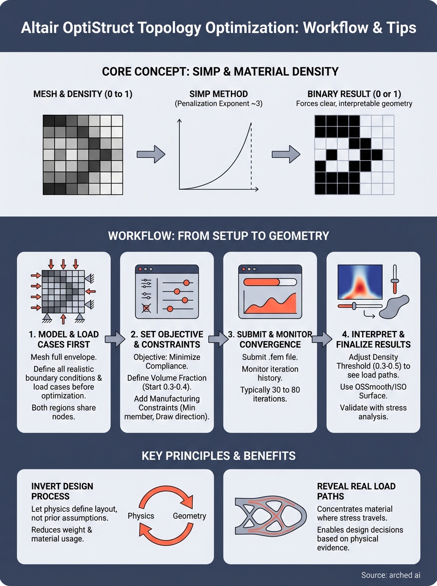
In OptiStruct, topology optimization treats material density as the design variable at every finite element in your model. Each element gets a density value between 0 and 1, where 0 means remove the material and 1 means keep it. The solver iterates, redistributing density across the design space to minimize an objective, typically structural compliance (the inverse of stiffness), subject to a volume fraction constraint you define upfront. The result is a material layout that carries load efficiently with as little mass as possible.
The SIMP method behind the scenes
OptiStruct uses the Solid Isotropic Material with Penalization (SIMP) method to push elements toward binary 0-or-1 values rather than leaving them in a gray zone. A penalization exponent, commonly set to 3, makes intermediate densities structurally inefficient, which forces the optimizer to commit to either full material or no material. This mathematical mechanism is what gives altair optistruct topology optimization its characteristic clarity in the final density plot, producing recognizable load paths instead of a blurry, ambiguous distribution.
The SIMP penalization exponent is the primary reason you get clean, interpretable geometry rather than a fuzzy gradient of density values.
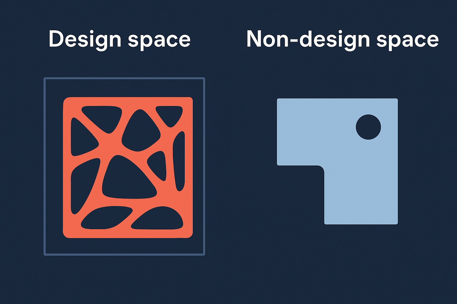
Design space versus non-design space
You split your model into two regions before running any analysis. The design space contains all the elements the optimizer can freely remove, and the non-design space holds geometry that must stay fixed, such as bolt holes, mounting surfaces, or load application points. Getting this split right is one of the most critical setup decisions, because elements placed in the wrong region either get removed incorrectly or prevent the solver from finding an efficient layout. Both regions must share nodes at their interface so loads transfer correctly across the mesh boundary. A poorly defined non-design space is one of the most common sources of unrealistic results.
Why topology optimization matters in real structures
Traditional structural design starts with experience and intuition, then verifies performance through analysis. That process works, but it limits your solution space to geometries you can already visualize. Topology optimization inverts this, letting physics define the material layout rather than your prior assumptions about what a structure should look like.
Weight reduction and material savings
When you apply altair optistruct topology optimization to a structural component, you often find that 20 to 40 percent of the original material contributes almost nothing to load transfer. Removing it cuts fabrication cost, shipping weight, and raw material consumption without touching structural performance. In high-volume manufacturing, those reductions compound significantly across the production run.
Every kilogram removed based on simulation evidence is a kilogram you didn't need to pay for, fabricate, or eventually recycle.
Identifying real load paths
Load paths in real structures are rarely where intuition suggests. Topology optimization makes them visible by concentrating material density along the actual routes stress travels through the part.
This clarity forces design decisions based on physical evidence rather than rules of thumb. You reduce the risk of over-engineering one region while unknowingly under-engineering another, which is a common and costly pattern in traditional hand-calculated designs.
How to run a topology optimization in OptiStruct
Running an altair optistruct topology optimization follows a consistent sequence: mesh the geometry, assign design and non-design regions, define load cases, set an objective function, and submit the job. Each step feeds directly into the next, so skipping or rushing any one of them produces outputs that mislead rather than inform.
Define your model and load cases first
Start by meshing the full design envelope in HyperMesh or your preferred preprocessor. Apply all realistic boundary conditions and load cases before touching any optimization settings, because the optimizer distributes material based on exactly the loads you specify. If a load case is missing, the resulting topology will not account for it, and you risk a structure that fails under real-world conditions.
Define every meaningful load case upfront; adding one after the fact changes the topology entirely and restarts your iteration count.
Set the objective and submit
In OptiStruct, open the optimization panel and set minimizing compliance as your objective. Assign the DESVAR and DVPREL cards to link your design variable, which is element density, to the model, then define a volume fraction response and constraint.
Once you confirm the setup, submit the .fem file and monitor convergence through the iteration history. OptiStruct typically converges in 30 to 80 iterations depending on mesh density and problem complexity.
Constraints and settings that shape the outcome
The volume fraction and manufacturing constraints you set before running altair optistruct topology optimization determine more about the final geometry than the mesh itself. Getting these settings right the first time saves you from rerunning the job multiple times just to correct avoidable errors.
Volume fraction target
Your volume fraction tells the solver what percentage of the original design space to retain. Set it too high and you keep unnecessary material; set it too low and the optimizer removes load-carrying structure to hit the target artificially. A starting value of 0.3 to 0.4 (30 to 40 percent of the original volume) works well for most structural components as a first-pass exploration.
Treat the volume fraction as a dial you adjust across two or three runs, not a fixed input you set once.
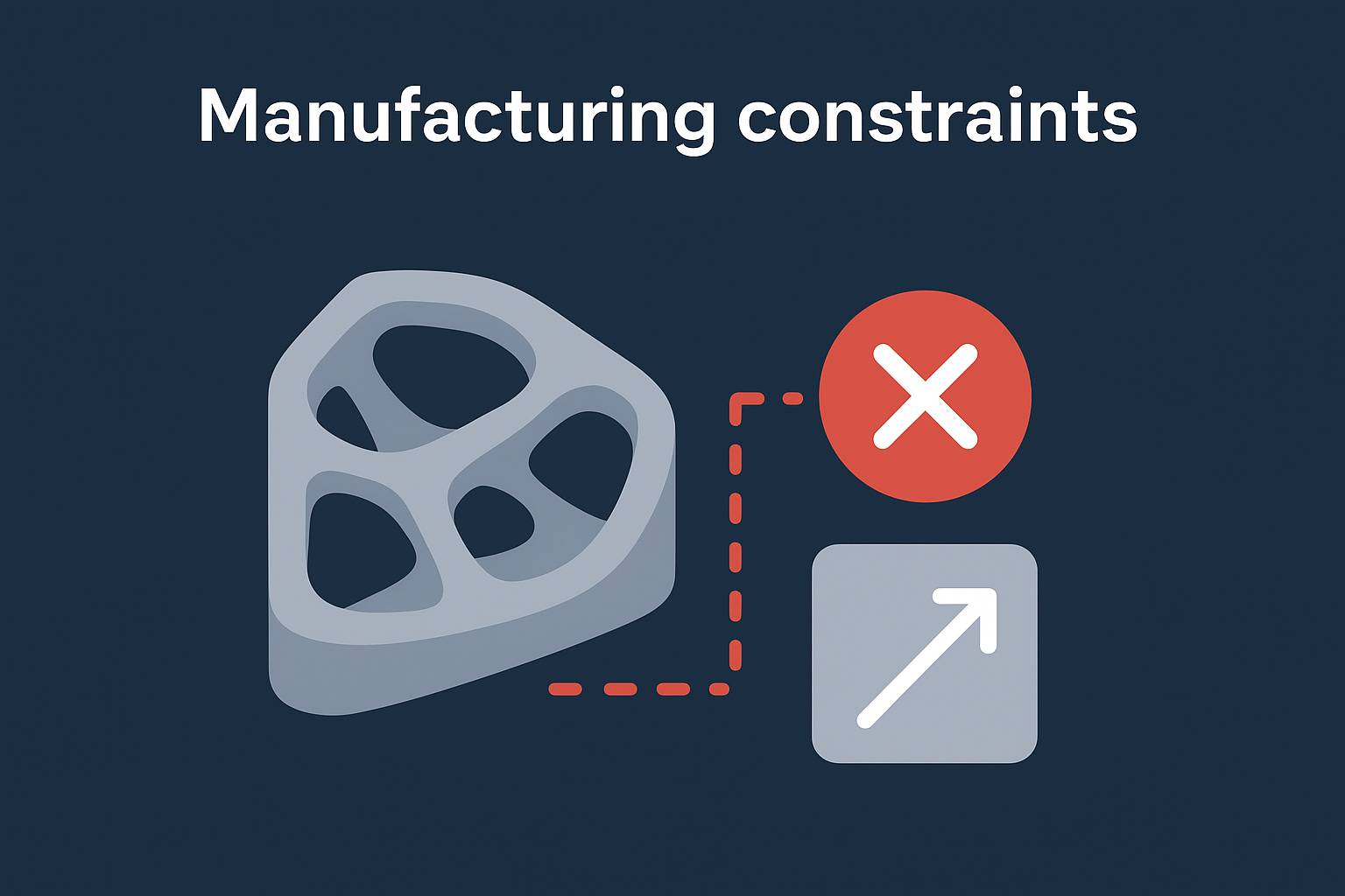
Manufacturing constraints
OptiStruct gives you several manufacturing constraint cards that prevent the optimizer from generating geometry you cannot actually build. The minimum member size constraint keeps thin, fragile features from appearing in the topology. Draw direction constraints enforce the kind of uniform cross-sections that casting and extrusion processes require. Apply these settings before you submit, because adding them mid-process forces a full restart and changes the density distribution significantly.
How to interpret results and finalize geometry
After altair optistruct topology optimization completes, OptiStruct writes a density field to an .h3d file you open in HyperView. The density plot shows a gradient from near-zero (gray, removable material) to near-one (solid, load-carrying material). Your job at this stage is to read that gradient critically, not accept it as a finished design.
Reading the density plot
Set your density threshold between 0.3 and 0.5 when you first visualize results. Elements below the threshold represent material the optimizer flagged as low-contribution, and those above form the primary load path you should preserve in your final geometry. Adjust the threshold up and down to confirm the load path stays continuous and recognizable.
A broken or scattered density plot at any threshold usually signals a poorly defined design space or a missing load case, not an accurate result.
Smoothing and exporting clean geometry
Once you confirm a clean load path, use OSSmooth or HyperMesh's ISO surface tool to extract a smooth geometric surface from the density field. Run a quick stress analysis on the extracted geometry to validate performance before committing to any CAD reconstruction. This verification step catches stress concentrations introduced during the smoothing process before they reach fabrication.
Next steps
You now have a complete picture of the altair optistruct topology optimization workflow, from SIMP penalization and design space setup through constraint tuning, result interpretation, and geometry extraction. The practical next step is to run a test case on a component you already know well, so you can validate your setup process against expected behavior before applying it to a high-stakes project. Start with a simple bracket or beam, confirm the density plot matches known load paths, then move to more complex geometry.
If your work centers on bridge structures, the same simulation-driven logic applies at a much larger scale. Manually iterating through beam configurations, pier layouts, and span arrangements to balance cost, carbon, and code compliance is slow and leaves value on the table. Arched automates that exploration across thousands of design variants so you can bid on optimized configurations instead of standard plan sets. Learn more about how it works on the Arched generative bridge design platform.