SOLIDWORKS Generative Design: Topology Optimization Guide
Master SOLIDWORKS generative design with this guide. Learn to run topology studies, reduce material costs, and turn optimized meshes into solid geometries.
SOLIDWORKS Generative Design: Topology Optimization Guide
SOLIDWORKS generative design enables engineers to move beyond manual iteration by letting algorithms explore thousands of possible geometries based on defined constraints and objectives. Instead of sketching one shape and hoping it works, you define loads, materials, and manufacturing methods, then let the software generate optimized solutions that meet your exact requirements. For anyone working in product development or mechanical engineering, this approach fundamentally changes how designs take shape.
This guide walks through how topology optimization works within SOLIDWORKS, what tools you'll need to access these features, and how to set up studies that produce manufacturable, high-performance parts. At Arched, we apply similar generative principles to bridge engineering, running thousands of physics-driven simulations to find optimal structural configurations. The underlying concept remains the same: automate the exploration of design possibilities so engineers can focus on decision-making rather than repetitive calculations. Here's how to put that concept into practice with SOLIDWORKS.
What SOLIDWORKS generative design means
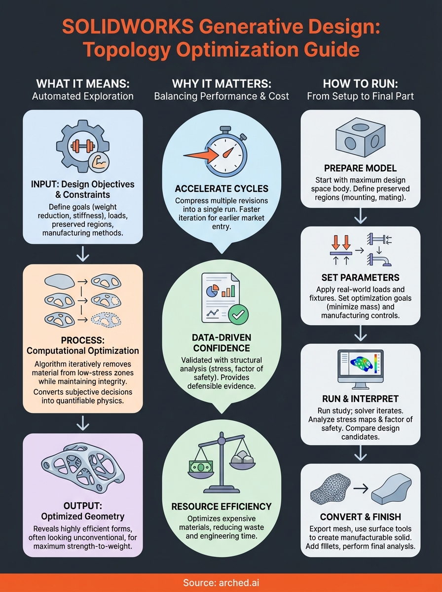
SOLIDWORKS generative design refers to a computational process that creates optimized part geometries by evaluating performance requirements against manufacturing constraints. You input design objectives like weight reduction or stiffness targets, specify where loads apply, define regions that cannot be modified, and select a manufacturing method. The algorithm then removes material from areas experiencing low stress while maintaining structural integrity in critical zones. This process runs automatically through multiple iterations until it converges on shapes that satisfy all your stated criteria.
The feature lives within SOLIDWORKS Simulation as a topology optimization study type. You work with an existing 3D model that represents your maximum design space, meaning the largest possible volume your part could occupy. From there, the software systematically evaluates which portions of that volume contribute to structural performance and which portions add unnecessary mass. Each iteration refines the geometry based on finite element analysis results, gradually revealing organic forms that often look nothing like conventionally designed parts.
How the algorithm works
You start by defining boundary conditions that mirror real-world use. This includes fixed faces where the part mounts to other components, applied forces representing operational loads, and any symmetry planes that reduce computational time. The algorithm applies strain energy density calculations across the entire design space, identifying low-stress regions where material removal won't compromise performance. It iteratively redistributes material to high-stress areas while eliminating it from low-stress zones until reaching your specified mass target or performance threshold.

The process converts subjective design decisions into quantifiable physics calculations, removing guesswork from structural optimization.
Manufacturing constraints directly shape the final geometry. If you select additive manufacturing, the algorithm produces complex lattice structures and organic curves impossible to machine. Choosing subtractive methods like milling forces the software to generate features that cutting tools can physically reach, eliminating internal voids and undercuts. This ensures you receive designs that your shop can actually produce without extensive post-processing or specialized equipment.
What makes it different from traditional CAD
Traditional modeling requires you to sketch profiles, extrude features, and manually evaluate whether each geometric decision meets structural requirements. You create a shape first, then test it through simulation to discover weaknesses. Generative approaches reverse this sequence by starting with performance requirements and letting physics determine the optimal form. Instead of testing one design, you simultaneously explore thousands of geometric variations that all satisfy your constraints.
Why topology optimization matters in SOLIDWORKS
Topology optimization addresses the fundamental challenge of balancing performance against material cost and manufacturing time. You no longer need to choose between lightweight designs and structural reliability because the algorithm finds geometries that maximize strength-to-weight ratios through mathematical analysis rather than educated guessing. This becomes critical when working with expensive materials like titanium or when every gram affects fuel efficiency in aerospace applications. The software eliminates the trial-and-error cycle that traditionally consumed weeks of engineering time.
Direct impact on product development cycles
SOLIDWORKS generative design compresses what used to take multiple design revisions into a single computational run. You define your constraints once, start the study, and receive multiple viable solutions ranked by how well they meet your objectives. This acceleration matters most during competitive bidding or tight development schedules where faster iteration means earlier market entry. Engineering teams can evaluate ten optimized variants in the time it previously took to manually refine one concept.
Automated optimization removes the bottleneck of sequential design-test-redesign loops that delay product launches.
Engineering confidence through data-driven validation
Every generated geometry comes with complete structural analysis data showing stress distribution, displacement values, and factor of safety calculations. You make decisions based on quantified performance metrics rather than intuition about what might work. This documentation also provides defensible evidence during design reviews or regulatory approval processes, demonstrating that your chosen geometry represents an optimal solution within defined constraints. The algorithm explores portions of the design space that human intuition typically overlooks, frequently revealing shapes that outperform conventional approaches while using less material.
What you need before you start
SOLIDWORKS generative design requires specific software packages and a properly configured model before you can run topology optimization studies. You cannot access these features with a standard SOLIDWORKS license alone, and attempting to set up a study with an incomplete model results in error messages that halt the entire process. Understanding these prerequisites saves time and prevents frustration when you're ready to generate optimized geometries.
Software and licensing requirements
You need SOLIDWORKS Simulation Professional or SOLIDWORKS Simulation Premium to access topology optimization capabilities. The base SOLIDWORKS package does not include these analysis tools. Your license must remain active with current maintenance to receive solver updates that handle complex mesh refinements during the optimization process. Check your subscription status through the SOLIDWORKS Installation Manager before starting any study setup, as expired licenses block access to simulation features entirely.
Topology studies consume significant computational resources, so verify your hardware meets the minimum specifications listed in SOLIDWORKS system requirements documentation.
Model preparation checklist
Your starting geometry must represent the maximum allowable design space rather than a finished part. This means creating a solid body that encompasses every possible location where material could exist in the final design. You'll designate preserved regions like mounting holes or mating surfaces that the algorithm cannot modify, plus load application points where forces act on the component. The model requires defined material properties since the solver calculates stress based on elastic modulus and yield strength values. Save the file in a dedicated project folder because topology studies generate multiple result files and intermediate geometries that quickly clutter your directory structure.
How to run topology optimization in SOLIDWORKS
SOLIDWORKS generative design studies start from the Simulation tab once you have your maximum design space model ready. You create a new study by selecting Topology Study from the study type dropdown, which opens a configuration panel different from standard static analysis setups. The interface asks you to specify optimization goals, manufacturing methods, and regions that must remain untouched throughout the process. Each decision you make here directly controls what geometries the algorithm can explore.
Setting up the study parameters
You begin by defining preserved regions through right-clicking the Preserved Regions folder in the study tree. Select faces or bodies that cannot change, like mounting holes, bolt patterns, or surfaces that mate with other components. Next, apply loads and fixtures exactly as you would in a static study, specifying forces, pressures, or moments at their actual application points. The algorithm uses these boundary conditions to calculate stress distribution across every iteration, so accuracy here determines result quality.

Specify the target mass reduction percentage or absolute mass value to control how aggressively the algorithm removes material.
Running the optimization
Under Manufacturing Controls, choose between additive, subtractive, or casting methods to constrain the geometry based on your production capabilities. Set the optimization goal to minimize mass while maintaining stiffness, or maximize stiffness within a target weight. Click Run Study and monitor the progress bar as the solver cycles through iterations, each one refining material distribution based on structural performance. The process typically completes in 30 minutes to several hours depending on model complexity and mesh density.
How to interpret results and finish the design
SOLIDWORKS generative design results appear as color-coded stress maps overlaid on the optimized geometry, showing exactly where the algorithm concentrated material and where it removed mass. You examine these visualizations to verify that maximum stress values remain below your material's yield strength and that no stress concentrations appear in critical areas. The results panel displays multiple design candidates ranked by how well they meet your stated objectives, letting you compare trade-offs between mass reduction and structural performance across different geometric solutions.
Reading the stress visualization
You identify high-stress regions shown in red or orange on the color scale, confirming they align with expected load paths rather than appearing in unexpected locations that indicate modeling errors. Check the displacement magnitude to ensure the part won't deflect beyond functional requirements under applied loads. The software calculates a factor of safety for each candidate geometry, giving you quantifiable confidence that the design withstands real-world conditions with appropriate margin.
Stress concentrations at sharp internal corners often require manual smoothing to prevent crack initiation during service life.
Converting to production geometry
The raw optimized shape exports as a mesh body that requires conversion into solid geometry your manufacturing processes can handle. You use the Smooth Mesh command to reduce surface irregularities, then employ Surface From Mesh tools to create boundary surfaces that you can thicken into manufacturable solids. This reconstruction step gives you control over final dimensions while preserving the structural efficiency the algorithm discovered. Add fillets and chamfers to eliminate stress risers the topology study revealed, then run a final static analysis on the cleaned-up geometry to confirm performance metrics still meet your requirements before releasing drawings to production.
Next steps
Running SOLIDWORKS generative design studies transforms how you approach structural optimization, but the process requires consistent practice to develop intuition about which parameters produce manufacturable results. Start with simple geometries where you understand the expected load paths, then gradually increase complexity as you become familiar with how the algorithm responds to different constraint combinations. Document your optimization settings and results for each project so you can reference successful configurations when tackling similar challenges.
Bridge engineers face analogous optimization problems at much larger scales, balancing structural performance against material costs and construction schedules. Arched applies the same generative principles you've learned here to bridge design, running thousands of physics-driven simulations to identify configurations that reduce costs while meeting safety standards. If you're working on infrastructure projects where automated optimization could accelerate your workflow, explore how Arched generates optimized bridge designs from plan sets.