Ansys Topology Optimization In Mechanical: Setup & Solvers
Learn to set up Ansys topology optimization studies to reduce weight and maximize stiffness. Master solvers, constraints, and CAD rebuild workflows.
Ansys Topology Optimization In Mechanical: Setup & Solvers
Engineers facing material constraints and weight targets often turn to Ansys topology optimization to discover geometries that manual design simply can't achieve. This computational method removes material from regions under low stress while preserving structural integrity, producing organic, load-path-driven shapes that maximize stiffness-to-weight ratios.
At Arched, we apply similar optimization principles to bridge engineering, running thousands of design iterations to balance cost, durability, and carbon impact. The underlying philosophy is the same: let simulation explore the design space rather than relying on intuition alone. Understanding how Ansys Mechanical handles topology optimization gives engineers a foundation for applying generative methods across infrastructure and product design.
This article covers the core setup process, solver options, and practical considerations for running topology optimization in Ansys Mechanical. You'll learn how to define objectives, apply manufacturing constraints, and interpret results that translate into manufacturable components.
Why topology optimization matters in Ansys Mechanical
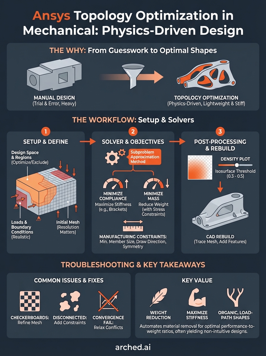
You face constant pressure to reduce weight without sacrificing strength, and traditional design approaches force you into time-consuming manual iterations. Topology optimization in Ansys Mechanical shifts this dynamic by automating the search for efficient material distribution. Instead of guessing which areas can lose material, you define performance targets and constraints while the solver mathematically determines where material contributes to load-bearing capacity.
Topology optimization replaces subjective design choices with physics-driven material removal, revealing optimal geometries that satisfy structural requirements at minimum weight.
Lightweighting without guesswork
Manual lightweighting involves removing material from suspected low-stress regions, then rerunning analysis to confirm assumptions. This trial-and-error process consumes engineering hours and rarely reaches true optimization. Ansys topology optimization inverts this workflow by starting from a full design envelope and systematically removing material based on stress distribution and compliance calculations. You specify a target mass reduction percentage, apply loads and boundary conditions, then let the solver identify which elements contribute least to structural performance.
Finding designs you wouldn't otherwise consider
The resulting geometries often display organic, branching structures that human intuition wouldn't naturally produce. These shapes follow load paths with mathematical precision, creating forms that look unusual but deliver measurable performance gains. Your role shifts from defining exact geometry to setting optimization parameters and manufacturing feasibility constraints. Engineers working on aerospace brackets, automotive suspension components, and industrial equipment housings use this approach to discover configurations that achieve 30-50% weight reduction while maintaining required safety factors.
What Ansys Mechanical can optimize and when to use it
Ansys Mechanical targets mass reduction, compliance minimization, and stiffness maximization as primary optimization objectives. You define the design space (the volume where material can be removed), apply loads and supports, then specify either a target mass fraction or a maximum compliance value. The solver distributes material to meet these goals while respecting your defined constraints.
Objectives you can target
You optimize for compliance (structural flexibility under load) or mass depending on your project requirements. Compliance minimization produces the stiffest structure for a given material volume, which works well for brackets, mounts, and load-bearing components. Mass minimization with stress constraints suits applications where weight drives performance, such as aerospace fittings or rotating machinery parts. Both approaches let you specify manufacturing constraints like minimum member size, draw direction for casting, or cyclic symmetry for rotational components.
Ansys topology optimization delivers the most value when you face strict weight targets but possess design freedom in geometry selection.
When topology optimization makes sense
You benefit from topology optimization when traditional design leaves substantial performance margin or when weight reduction directly impacts system-level metrics like fuel consumption or payload capacity. Skip this approach if your geometry is already tightly constrained by packaging requirements or if manufacturing processes limit your ability to produce complex shapes. Early-stage design with flexible envelope definitions and multiple load cases produces the strongest candidates for topology optimization workflows.
How to set up a topology optimization study in Mechanical
You launch a topology optimization study by inserting the Topology Optimization module into your existing static structural analysis. This workflow requires a fully defined finite element model with loads, supports, and material properties before you activate optimization. The process involves defining optimization regions (where material can be removed), exclusion regions (areas that must remain solid), and manufacturing constraints that ensure the final geometry can actually be produced.
Design space and optimization regions
Start by selecting the design volume where Ansys can redistribute or remove material. You define this through named selections or body selections within your geometry tree. Exclude critical features like bolt holes, mounting surfaces, or connection points by creating exclusion regions that remain untouched during optimization. The solver only modifies elements within your defined optimization region, treating excluded zones as fixed geometry that must remain in the final design.
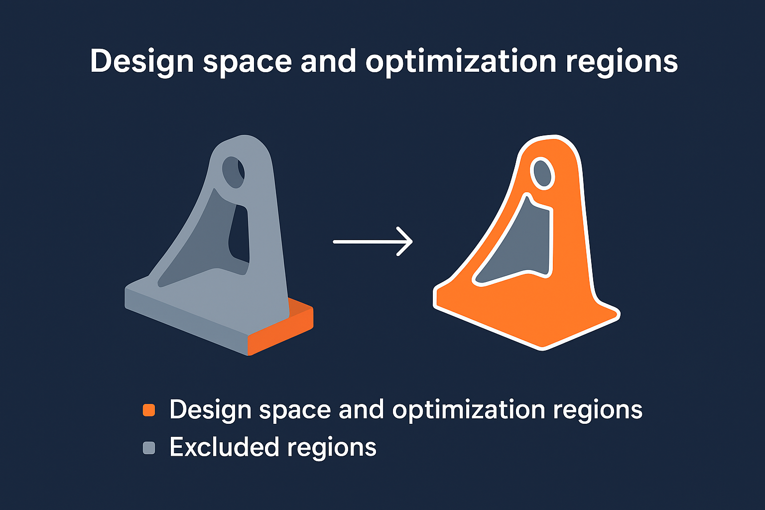
Proper design space definition determines whether your optimized result will be manufacturable or require extensive manual cleanup.
Applying loads and boundary conditions
Your optimization results depend entirely on how accurately you represent service loads and support conditions. Apply all relevant load cases that the component will experience during operation, including thermal loads if temperature affects structural performance. Boundary conditions must reflect realistic constraints rather than arbitrary fixture locations, since the optimizer interprets every applied condition as a performance requirement that shapes the final material distribution.
Solvers, objectives, and constraints in Mechanical TopOpt
Ansys topology optimization relies on the Subproblem Approximation Method to iteratively adjust element densities until convergence criteria are met. You specify an objective function (typically minimize compliance or mass), then define constraints that limit the solution space. The solver evaluates stress distributions and material efficiency across thousands of elements, gradually removing density from underutilized regions while respecting your defined limits.
Setting up optimization objectives
You choose between minimizing compliance (maximizing stiffness) or minimizing mass as your primary objective. Compliance minimization produces the stiffest structure possible for a given material volume, which suits applications where deflection limits drive design. Mass minimization with stress or displacement constraints works when weight reduction takes priority over absolute stiffness. Both approaches require you to specify a retention percentage (how much of the original volume remains) or a target mass value that guides the solver toward your design goals.
The objective you select fundamentally shapes the optimized topology, with compliance-driven results favoring structural rigidity and mass-driven results emphasizing material efficiency.
Manufacturing and geometric constraints
You apply manufacturing constraints to ensure the optimized geometry can actually be produced using your intended fabrication method. Minimum member size prevents the solver from creating features too thin to manufacture reliably. Draw direction constraints enforce draft angles for casting or molding processes, while cyclic symmetry ensures rotational components maintain balanced mass distribution. Constraint definitions directly affect computational time and result complexity, so you balance manufacturing realism against solution convergence requirements.
Post-processing, CAD rebuild, and manufacturing rules
Your ansys topology optimization produces a density distribution where elements range from full material (density = 1) to void (density = 0). Post-processing involves setting an isosurface threshold (typically 0.3 to 0.5) that determines which elements remain in the final geometry. Ansys displays this result as a smoothed surface that you export as an STL or STEP file, but this mesh-based output requires conversion into parametric CAD before manufacturing.
Reading density plots and interpreting results
You examine the density gradient to identify load paths and material concentration patterns that reveal structural behavior. Elements below your threshold get hidden, leaving a geometry that shows where material contributes most to your optimization objective. The transition zones between solid and void regions indicate areas where the solver balanced competing requirements. Export the smoothed geometry at your chosen density cutoff, recognizing that lower thresholds retain more material while higher values produce lighter but potentially weaker structures.
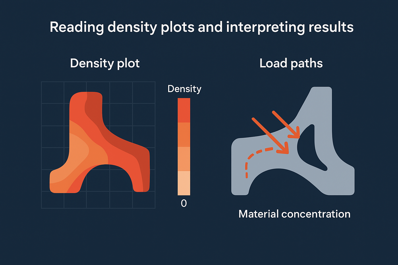
Manufacturing constraints applied before optimization prevent impractical features, but post-processing cleanup still requires engineering judgment to ensure producibility.
Converting optimized mesh to parametric CAD
Imported STL files from topology optimization lack the parametric features needed for detailed design work or manufacturing documentation. You trace the optimized shape manually in your CAD system using the STL as a reference, creating sketch-based features that approximate the organic forms while adding necessary manufacturing details like radii, draft angles, and mounting features.
What to do when results look wrong
Your optimized geometry sometimes produces checkerboard patterns, disconnected islands, or unrealistic material distributions that signal setup errors rather than valid solutions. These artifacts stem from mesh resolution issues, conflicting constraints, or poorly defined optimization parameters. You diagnose problems by systematically reviewing your mesh quality, boundary conditions, and convergence settings before rerunning the analysis.
Fixing checkerboard patterns and disconnected regions
Checkerboard artifacts appear when your mesh density proves too coarse for the optimization algorithm to resolve proper material transitions. Refine your mesh in the design space region, targeting element sizes that capture geometric features you expect in the final result. Disconnected material islands indicate either insufficient manufacturing constraints or unrealistic load cases. Apply minimum member size controls or symmetry constraints to force connected topology, then verify that your applied loads represent actual service conditions rather than idealized point forces.
Mesh refinement and manufacturing constraints eliminate most optimization artifacts, but you still verify that boundary conditions reflect physical reality.
Resolving convergence and constraint conflicts
Your solver may fail to converge when competing constraints create impossible requirements, such as mass targets that conflict with stress limits. Review the optimization log for constraint violation warnings, then relax either your mass retention target or your maximum stress value. Increase iteration limits if the solution shows improvement but hasn't stabilized, recognizing that ansys topology optimization requires 30-50 iterations for complex geometries with multiple manufacturing constraints.
Key takeaways
Ansys topology optimization transforms weight reduction from guesswork into a physics-driven process that mathematically identifies optimal material distribution. You define the design space, apply realistic loads and constraints, then let the solver explore thousands of configurations that manual design wouldn't consider. The workflow requires proper mesh resolution, manufacturing constraints, and accurate boundary conditions to produce manufacturable results.
Your optimized geometry needs conversion from mesh output to parametric CAD before production, which involves tracing the organic forms and adding necessary manufacturing features. Post-processing decisions like isosurface threshold selection directly affect the final weight-to-strength ratio, so you balance aggressive material removal against structural requirements.
Bridge engineers face similar optimization challenges when balancing cost, durability, and carbon impact across thousands of design variations. Arched's generative platform automates this analysis for bridge infrastructure, letting you bid on optimized designs rather than standard plan sets.