SOLIDWORKS Topology Optimization: Setup, Run, And Interpret
Master SOLIDWORKS topology optimization. Learn to set up design spaces, apply constraints, and turn organic results into refined, manufacturable CAD parts.
SOLIDWORKS Topology Optimization: Setup, Run, And Interpret
Engineers often spend hours manually iterating on part geometry, trimming material here, adding reinforcement there, hoping to land on something that balances weight and strength. SOLIDWORKS topology optimization flips that process. Instead of guessing, you define your constraints and let the software compute where material actually needs to exist, and where it doesn't. The result is a mathematically-driven starting point for lighter, stronger, more efficient components.
This guide walks you through the complete workflow: setting up a topology study in SOLIDWORKS Simulation, configuring goals and constraints, running the analysis, and interpreting the organic shapes it produces. You'll learn how to turn those results into manufacturable geometry.
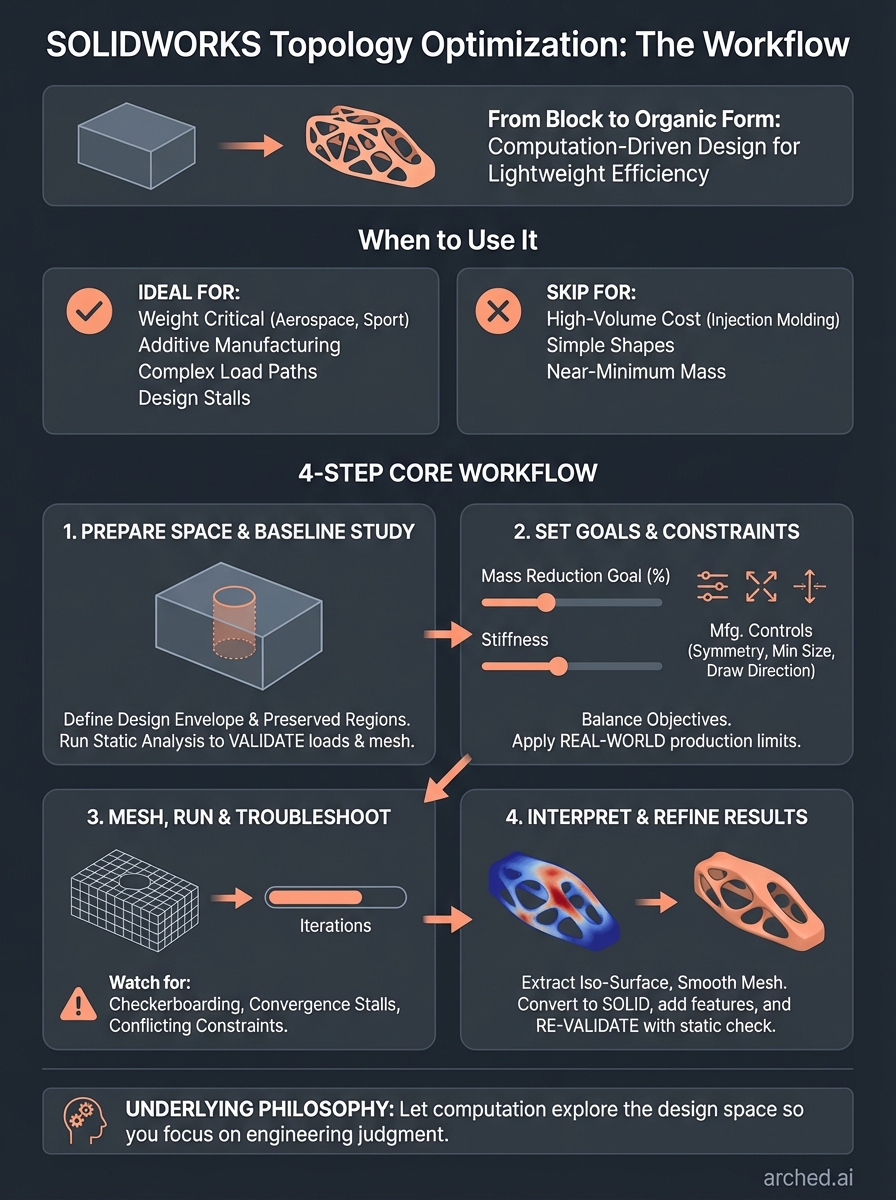
At Arched, we apply similar generative engineering principles to bridge design, running thousands of simulations to find optimal configurations that manual methods would miss. Whether you're optimizing a bracket in SOLIDWORKS or a 200-foot span, the underlying philosophy is the same: let computation explore the design space so you can focus on engineering judgment where it matters most.
What SOLIDWORKS topology optimization does and when to use it
SOLIDWORKS topology optimization removes material from a design space based on load paths and structural requirements you define. You start with a block of material (your design space), apply forces and constraints, then let the solver iteratively remove mass from low-stress regions while preserving stiffness where the part actually needs it. The output is an organic, lattice-like geometry that looks nothing like traditional machined parts but represents the most efficient distribution of material for your specific loading conditions.
Core mechanics of the optimization process
The solver runs finite element analysis in a loop, calculating stress distribution across the entire design space. After each iteration, it removes elements from regions below a stress threshold, then recalculates. This continues until it reaches your target mass reduction or until removing more material would violate your stiffness or safety factor requirements. You control the final shape by setting manufacturing constraints (like minimum member size, draw direction for molding, or symmetry requirements) so the result can actually be produced.
Topology optimization doesn't just lighten parts. It reveals load paths you wouldn't intuitively design by hand.
When to deploy topology optimization
You should run a topology study when weight matters more than cost or when you're designing for additive manufacturing where complex geometries don't increase production expense. The process makes sense for aerospace brackets, motorsport components, medical implants, or any scenario where removing a few grams justifies the extra engineering time. It's also valuable when you're stuck in a design loop, manually tweaking a part that needs to be 30% lighter but you don't know where to start cutting material.
Skip topology optimization if you're working with high-volume injection molding where conventional shapes are cheaper to tool, or if your part is already close to its theoretical minimum mass. The organic forms it generates often require post-processing to turn into manufacturable CAD, so factor that effort into your decision. Use it as a concept generation tool, not a final geometry output.
Step 1. Prepare your design space and baseline study
You need to create a design space volume before SOLIDWORKS can optimize anything. This means modeling a block of material that represents the maximum envelope your part can occupy. Think of it as the starting mass the software will carve away from. You also need preserved regions (mounting holes, interface surfaces, etc.) that must remain untouched. Run a baseline static analysis first to confirm your loads, fixtures, and mesh settings produce valid results. If your static study fails or shows unrealistic stress concentrations, your topology study will inherit those problems and waste hours on bad data.
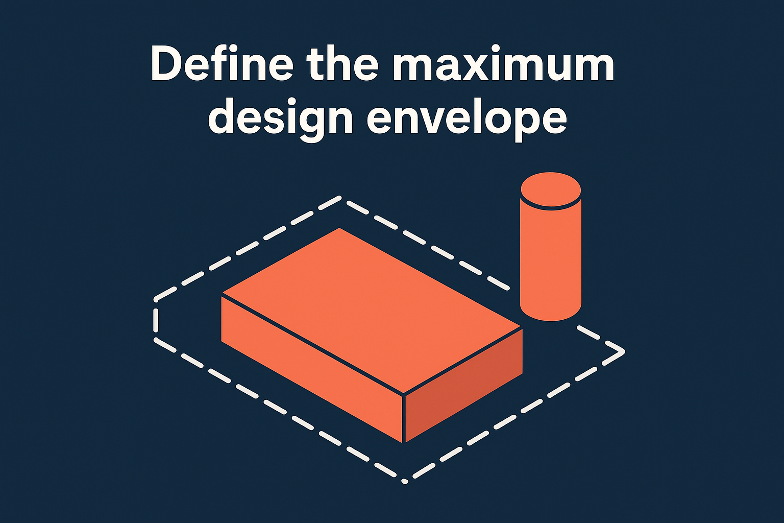
Define the maximum design envelope
Start with a simple rectangular or cylindrical body that encompasses the space between your fixed mounting points and load application surfaces. Model this as a separate solid body in the same part file. You'll designate this body as the design space in the topology study setup. Keep preserved regions as distinct bodies: bolt holes, mating surfaces, or any geometry that interfaces with other components. These stay fixed while the solver removes material from the design space body. Avoid creating an oversized envelope just because you can. The larger the design space, the longer the solve time and the more post-processing you'll need to extract usable geometry.
Run a standard static analysis first
Before launching a topology study, create a static structural analysis using the exact loads and fixtures you plan to apply. Verify that your mesh converges, your safety factors are reasonable, and your boundary conditions represent real-world constraints. This baseline study validates your setup and gives you a reference point for comparing the optimized design. If the static analysis shows a maximum stress of 150 MPa under your load case, you'll want your topology result to stay below that threshold after material removal.
A clean baseline study prevents you from optimizing a flawed model and wasting compute time on garbage inputs.
Step 2. Set goals, constraints, and manufacturing controls
Once your baseline static study validates, you configure the topology study parameters that tell SOLIDWORKS how aggressively to remove material and what physical constraints to respect. This step determines whether your output is a sculptural mess or something you can actually manufacture. You balance competing objectives (maximize stiffness, minimize mass) and apply manufacturing rules (minimum wall thickness, symmetry planes, draft angles) that prevent the solver from creating geometries your production process can't handle.
Define your optimization objectives
Set your mass reduction goal as a percentage of the original design space volume. A typical first pass targets 30-50% reduction, though aerospace applications may push 70% or higher. You also define a best stiffness goal to prevent the part from becoming too flexible as material disappears. SOLIDWORKS lets you prioritize these objectives by assigning weights, so you control whether the solver favors lighter weight over structural rigidity or vice versa. Always keep your safety factor from the baseline study in mind when setting these targets.
Apply manufacturing constraints
Manufacturing controls tell the solver what shapes it can actually create. Symmetry constraints force identical geometry across a plane, useful for parts with balanced loading. Minimum member size prevents thin webs your process can't produce (set this to 2-3 times your minimum wall thickness for casting or 3D printing). For molded parts, apply a demold direction so features pull cleanly from the tool. Add pattern repetition if you need repeating structures for lattice designs.
Manufacturing constraints transform organic blobs into producible parts before you waste time on post-processing.
Common constraints for different processes:
- CNC machining: Symmetry, minimum radius, accessibility direction
- Additive manufacturing: Minimum member size, overhang angle limits
- Casting/molding: Demold direction, minimum draft angle, split line location
Step 3. Mesh, run, and troubleshoot common failures
Your mesh settings directly impact both solve time and result quality in SOLIDWORKS topology optimization. A coarse mesh runs faster but produces blocky, unusable geometry. A fine mesh reveals smoother load paths but can take hours to solve on complex design spaces. You need to balance resolution against computation time, starting with a medium density mesh (4-6mm element size for typical bracket-scale parts) and refining only if the initial results show excessive jaggedness in critical load-bearing regions.
Apply mesh controls to the design space
Create a curvature-based mesh on your design space body with a maximum element size of 5mm and minimum of 2mm for parts under 300mm in any dimension. Set mesh quality to high. Avoid using adaptive mesh refinement in topology studies because the solver needs consistent element density to properly evaluate material removal across the entire volume. Apply local mesh control only to preserved regions with complex geometry (bolt holes, fillets) where stress concentrations matter.
Run the study and watch for failure modes
Right-click your topology study and select Run. The solver displays iteration progress in the status bar. A typical study completes 30-50 iterations depending on your mass reduction target. Monitor the objective graph to confirm stiffness and mass values converge. If the solver stops with "no solution" errors, you've likely set conflicting constraints (example: 70% mass reduction with demold direction and symmetry often creates impossible geometry). Relax one constraint or reduce your mass target by 10% and rerun.

Failed topology studies usually mean your manufacturing constraints are too restrictive for the mass reduction you're demanding.
Common failure patterns:
- Checkerboarding: Lower minimum member size to 3-4 times element size
- Convergence stalls: Reduce mass target or increase allowed iterations
- Disconnected regions: Add connectivity constraints or increase member size
Step 4. Interpret results and turn them into a final part
The topology study output shows a density plot where blue regions represent material the solver wants to remove and red regions indicate critical load paths. You need to convert this color-coded visualization into solid CAD geometry you can manufacture. SOLIDWORKS provides an iso-surface tool that generates a body from the density threshold you specify, typically between 0.3-0.5 (30-50% material retention). This extracted geometry will look organic and rough, requiring manual smoothing and feature addition before you can send it to production.
Extract and smooth the optimized geometry
Right-click your topology study results and select Smooth Mesh. Set your density threshold to match your mass reduction goal (if you targeted 40% reduction, use 0.4). Click OK to generate a mesh body representing the optimized shape. Convert this mesh to a solid body using Insert > Mesh > Surface from Mesh, then thicken or fill to create manufacturable geometry. You'll need to manually add chamfers, fillets, and mounting features back onto the smoothed form since the solver strips these details during optimization.
The extracted geometry is a concept, not a final design. You still apply engineering judgment to make it producible.
Validate the redesigned part
Run a final static analysis on your smoothed geometry using the same loads from your baseline study. Compare maximum stress and displacement values to confirm the optimized part maintains your required safety factors. If stress concentrations exceed your baseline by more than 15%, add local reinforcement or increase your density threshold and re-extract. This validation loop ensures your solidworks topology optimization actually improved performance rather than creating a fragile sculpture that fails under real loads.
Next steps
You now have the complete solidworks topology optimization workflow from design space setup through validation. Start with a simple bracket or mounting component where weight reduction matters. Run your first study with conservative constraints (30% mass reduction, clear manufacturing limits) to build confidence before tackling complex assemblies. Keep your baseline static analysis file as a reference point for comparing optimized results against your original design.
The same computational principles that drive topology optimization in SOLIDWORKS apply at larger scales. Arched applies generative engineering to bridge infrastructure, running thousands of physics-based simulations to find optimal configurations that manual methods miss. Our platform automates the exploration of design variations while maintaining code compliance and safety standards. If you're ready to see how this approach transforms civil infrastructure projects, explore how Arched optimizes bridge designs using deep simulation and multi-objective scoring.