Drilled Shafts for Bridge Foundations: Design & Construction
Master the design and construction of drilled shafts for bridge foundations. Explore AASHTO LRFD specs, geotechnical requirements, and integrity testing.
Drilled Shafts for Bridge Foundations: Design & Construction
Drilled shafts for bridge foundations are one of the most widely specified deep foundation systems in U.S. highway and infrastructure projects. Their ability to transfer heavy structural loads through weak or variable soils down to competent rock or bearing strata makes them a go-to choice when driven piles can't meet design demands, whether due to site constraints, seismic requirements, or sheer load magnitude.
But designing a drilled shaft isn't a simple calculation. Engineers must balance geotechnical uncertainty, AASHTO LRFD specifications, constructability risks, and cost, all while meeting strict FHWA and state DOT standards. A single bridge bent might involve dozens of feasible shaft configurations, and choosing the right one has a direct impact on both project budget and long-term structural performance. This is exactly the kind of multi-variable engineering problem that Arched was built to solve, using generative design and deep simulation to evaluate thousands of foundation and superstructure combinations and surface the most optimal candidates for engineer review.
This article breaks down the core principles behind drilled shaft design and construction for bridges. We'll cover geotechnical investigation requirements, structural design procedures, FHWA construction guidelines, load testing methods, and how drilled shafts compare to alternative deep foundation systems so you can make well-informed decisions on your next bridge project.
Why bridge teams choose drilled shafts
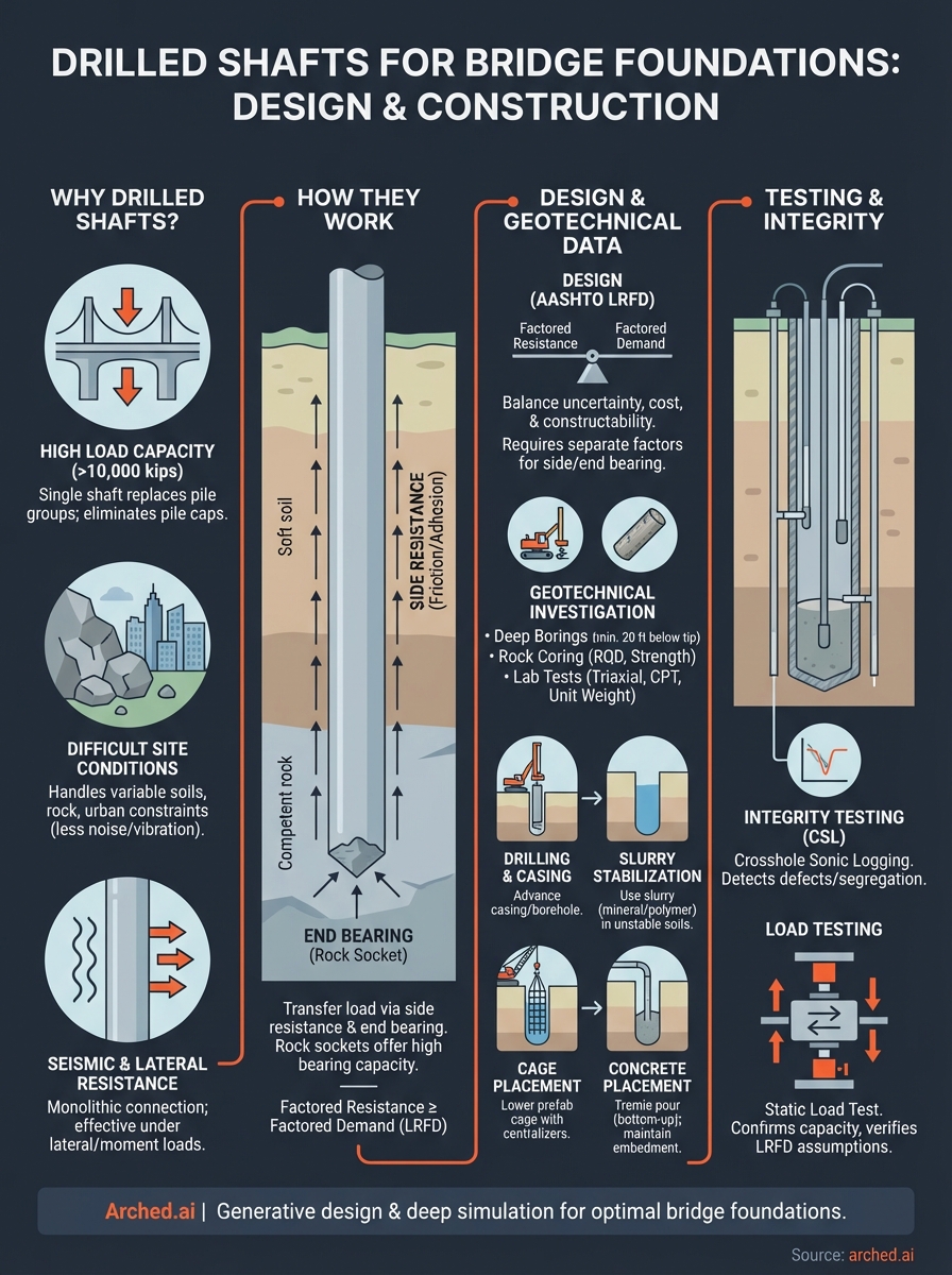
Drilled shafts dominate deep foundation specifications on major bridge projects for practical reasons, not preference. When your site combines heavy axial loads, problematic subsurface conditions, or tight urban constraints, driven pile installation simply cannot deliver what a large-diameter drilled shaft can. Understanding the specific advantages helps you defend your foundation selection during design review and avoid costly changes during construction.
Load capacity that driven piles can't match
A single drilled shaft can carry axial loads exceeding 10,000 kips in the right geologic conditions, a threshold that would require a cluster of 20 or more driven piles to match. That concentrated capacity comes from two mechanisms working together: end bearing on competent rock or dense soil, and side resistance developed along the full shaft length. When your bridge has large column loads concentrated at individual bents, a single large-diameter shaft per column eliminates the need for a pile cap entirely, which cuts concrete volume and reduces excavation depth at the footing.
For contractors, fewer foundation elements also means fewer operations to track, inspect, and document. Fewer elements per bent directly reduces schedule risk on projects where the foundation phase sits on the critical path.
A single 6-foot-diameter drilled shaft socketed into rock can replace an entire driven pile group, eliminating the pile cap and saving weeks of foundation work on a typical pier.
Performance in difficult site conditions
Drilled shafts for bridge foundations are often the only practical solution when site conditions make driving impossible or cost-prohibitive. Boulders, hard rock near the surface, and variable fill layers all create refusal problems for driven piles. A drill rig can advance through those materials with the right tooling: roller bits for rock, core barrels for cobbles, and steel casing to stabilize collapsing soils.
Urban bridge replacements add another layer of complexity. Driven pile installation generates vibration and noise that can damage adjacent structures or violate local ordinances near hospitals, schools, or sensitive utilities. A drilled shaft, installed with a rotary drill rig and minimal ground disturbance, sidesteps those constraints without requiring a variance or a noise study appeal.
Sites with artesian groundwater or running sands also benefit from drilled shaft construction. Your team can use a bentonite or polymer slurry to stabilize the borehole during drilling and concrete placement, maintaining borehole integrity without dewatering an entire work zone.
Seismic and lateral load resistance
In seismic zones, lateral load and moment demand at the foundation level often controls design more than axial load. Drilled shafts carry a structural advantage here because their large diameter and continuous reinforcement cage create a ductile, moment-resistant connection between the column and the foundation soil. The shaft effectively acts as an extension of the column below grade.
Both AASHTO LRFD and Caltrans SDC allow designers to model the shaft and column as a single structural element for seismic analysis. This continuity simplifies detailing and reduces the number of construction joints where seismic damage typically initiates. For bridges in Seismic Design Categories C and D, the ability to develop plastic hinging in a predictable location is a meaningful performance advantage over shallow or pile-supported foundations.
Drilled shafts also perform well under scour conditions. Because your shaft extends deep below the streambed, even significant scour events do not reduce lateral stiffness to the point of instability, provided your design accounts for reduced soil support at the scoured section.
How drilled shafts work in bridge foundations
Drilled shafts for bridge foundations transfer structural load to competent soil or rock through two distinct mechanisms: side resistance along the shaft length and end bearing at the shaft tip. Understanding how each mechanism activates, and how they interact, directly affects how you proportion a shaft and what geotechnical parameters your design requires.
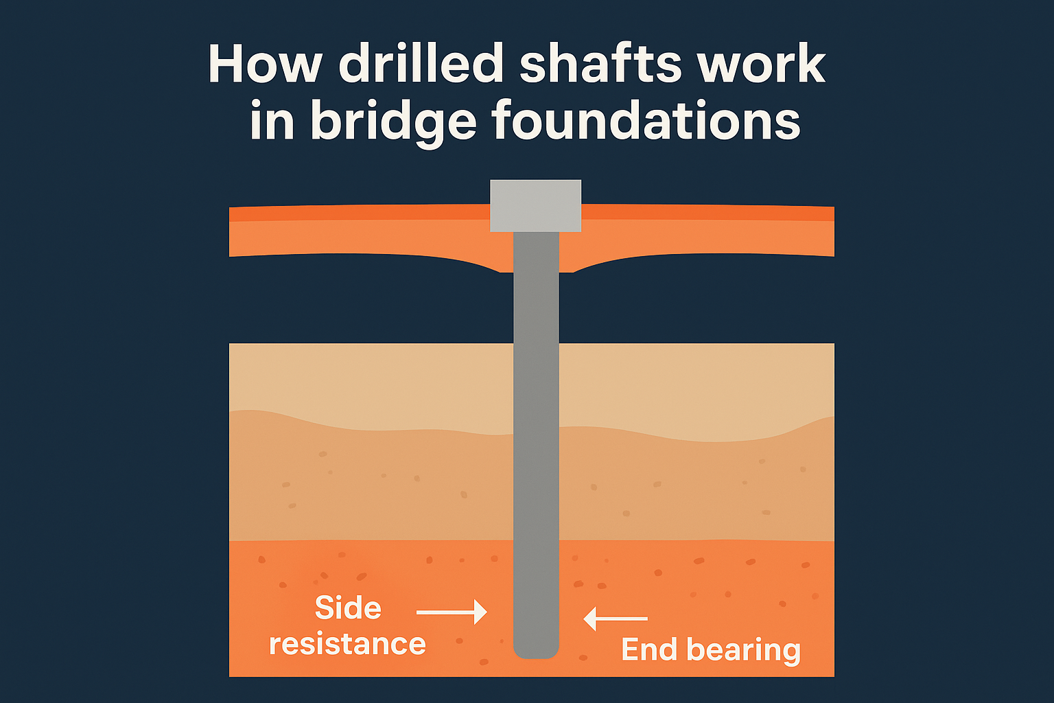
Side resistance and end bearing
Side resistance develops as the shaft moves downward relative to the surrounding soil. Friction and adhesion along the bored surface generate a distributed upward force that resists the applied axial load. In cohesive soils, this resistance depends on undrained shear strength. In cohesionless soils and rock sockets, it depends on interface friction angle and normal stress acting on the shaft wall.
End bearing activates at the base of the shaft when downward displacement transfers load directly to the bearing stratum. Rock sockets generate the highest end-bearing values, often exceeding 100 ksf in competent limestone or granite. In most bridge foundation designs, side resistance mobilizes first at smaller deflections, while full end bearing requires slightly more movement to develop. Your design must account for this sequential activation when you set resistance factors under AASHTO LRFD.
In rock-socketed shafts, side resistance alone can carry the full design load, which means end bearing serves as reserve capacity rather than a primary load path.
Structural behavior under lateral and moment loads
Bridge columns transfer not just vertical load but also significant lateral forces and overturning moments from wind, braking, and seismic events. The drilled shaft resists these through passive soil pressure distributed along the embedded length. Depth of embedment and shaft diameter both control stiffness: a larger-diameter shaft deflects less per unit of lateral load, and deeper embedment engages more soil mass.
Reinforcement continuity between the column cage and the shaft cage is what makes drilled shafts effective under combined loading. The reinforcement runs uninterrupted through the column-shaft interface, creating a monolithic structural element. This eliminates a construction joint at the most critically loaded location and allows the system to behave as a single cantilever fixed into the ground, which is exactly how seismic analysis models it. Your structural engineer must design the lap splice and bar development lengths at this interface to full moment capacity.
How to design drilled shafts with LRFD
AASHTO LRFD Bridge Design Specifications govern how you size and proportion drilled shafts for bridge foundations in the United States. The Load and Resistance Factor Design framework requires you to factor both loads and resistances separately, rather than applying a single global safety factor. That distinction matters because geotechnical resistance carries more uncertainty than structural resistance, and LRFD makes you account for that difference explicitly in your calculation chain.
Resistance factors and limit states
AASHTO LRFD Section 10 defines separate resistance factors for side resistance and end bearing, and those factors differ depending on whether your design relies on static analysis methods, load test data, or dynamic testing results. For a shaft designed using only soil boring data without a load test, side resistance factors for cohesive soil typically fall around 0.45 to 0.55, and end bearing factors for rock sockets sit near 0.50. When you run a static load test at the site, those factors increase significantly because you've reduced geotechnical uncertainty directly.
Running a static load test on a production shaft or test shaft can raise your resistance factor by 20 to 30 percent, which often justifies the test cost on projects with five or more shafts per bent.
Your design must satisfy both the strength limit state and the service limit state. The strength limit state controls shaft diameter and depth by requiring that factored resistance equals or exceeds factored demand. The service limit state controls settlement, limiting total head displacement to values your bridge superstructure can tolerate, typically 1 inch or less at the column base for most DOT specifications.
Sizing the shaft for axial and lateral demand
Lateral load design runs through p-y curve analysis, where you model the soil as a series of nonlinear springs resisting shaft deflection at each depth increment. Programs that implement this method let you test different shaft diameters and embedment depths against your lateral demand until deflection and moment stay within acceptable limits. Your reinforcement cage must develop full moment capacity at the column-shaft interface, so bar size and spacing decisions follow directly from the maximum moment your p-y analysis produces.
Both axial and lateral checks feed into your final shaft geometry. You select the diameter that satisfies lateral stiffness first, then confirm that the resulting shaft area and socket length provide adequate axial resistance under factored loads at the strength limit state.
What geotechnical data drilled shafts need
Every drilled shaft design is only as reliable as the geotechnical investigation behind it. Inadequate subsurface data leads to conservative designs that waste material, or worse, unconservative ones that fail to meet AASHTO resistance requirements once field conditions deviate from your assumptions. Before you finalize shaft dimensions, you need a site investigation program that resolves the specific soil and rock parameters your LRFD calculations depend on.
Boring depth, spacing, and rock coring
Your borings must extend at least 20 feet below the anticipated tip elevation of each shaft, or a minimum of two shaft diameters below the tip, whichever is deeper. That requirement comes directly from FHWA Geotechnical Engineering Circular No. 10, which sets the benchmark for drilled shaft investigation programs on bridge projects. One boring per shaft location is the standard for major bridge piers, though you can consolidate to one boring per bent on smaller structures if the subsurface profile appears consistent across the site.
For rock-socketed shafts, rock coring is not optional. You need continuous NQ or HQ core samples through the socket zone to document rock quality designation (RQD), unconfined compressive strength, and discontinuity spacing. Those values feed directly into your side resistance and end-bearing calculations, and a DOT reviewer will expect to see core photographs alongside your boring logs.
A single boring that stops at rock refusal without coring tells you almost nothing about socket length or end-bearing capacity.
Soil and rock parameters for resistance calculations
Drilled shafts for bridge foundations rely on a specific set of lab and field test results to quantify side resistance and end bearing in each soil or rock layer. For cohesive soils, undrained shear strength from unconsolidated-undrained triaxial tests or field vane shear gives you the alpha method input your side resistance calculation needs. For cohesionless soils, standard penetration test N-values and cone penetration test sleeve friction values feed into the beta method.
Your lab program should also include unit weight and moisture content at minimum for every sampled interval, with consolidation tests on soft clay layers where settlement governs design. For rock, unconfined compressive strength tests on intact core specimens let you apply AASHTO's rock socket resistance factors directly. Collect at least five strength tests per rock unit so you can use a characteristic value rather than a single data point, which is what most DOT specifications require before they accept your resistance calculations.
How drilled shafts get built on site
Construction sequence controls quality on drilled shaft projects more than any other factor. A single misstep during drilling, slurry management, or concrete placement can introduce a defect that no amount of post-pour testing will fix. Knowing the standard construction sequence and where failures concentrate helps you write tighter specs and catch problems before the concrete truck arrives.
Drilling, casing, and borehole stabilization
Your crew starts by advancing a temporary steel casing through the upper soils to prevent the borehole collar from caving into the excavation. Casing diameter matches the shaft diameter, and your drill rig advances it using oscillation or vibration while simultaneously drilling inside it. Once you're through the unstable surface soils and into competent material, you have a decision to make: advance the hole dry, use water, or stabilize with a mineral or polymer slurry.
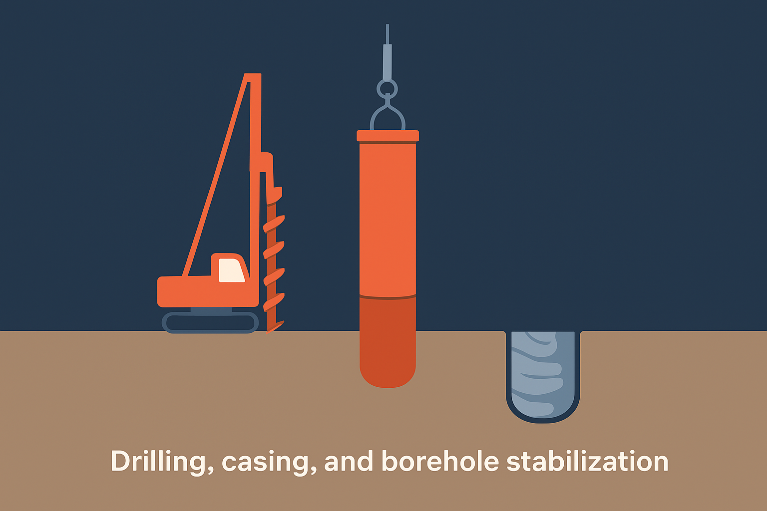
Dry construction works only in stiff cohesive soils or rock where the borehole wall stands on its own without support. In cohesionless soils, saturated clays, or any zone with groundwater above the tip, you need slurry to keep the borehole open. Mineral slurry (bentonite) forms a filter cake on the borehole wall that holds back groundwater and loose soil. Polymer slurry maintains borehole stability through viscosity rather than filter cake formation, and it leaves a cleaner shaft wall when you're ready to place concrete.
Slurry that is not properly desanded or that degrades before concrete placement can contaminate the concrete-soil interface and reduce side resistance by 30 percent or more in cohesionless soils.
Reinforcement cage placement and concrete
Once your drill crew confirms the tip elevation and cleans the base of loose cuttings, you lower the prefabricated reinforcement cage into the slurry-filled hole using a crane. Cage centralizers hold the steel off the borehole wall so your cover requirements are met on all sides. Your inspector checks cage depth and confirms centralizer spacing before you call for concrete.
Concrete placement uses a tremie pipe lowered to the shaft tip, not poured from the surface. You charge the tremie with a concrete plug, then raise it slowly as concrete fills upward from the bottom. This bottom-up placement displaces slurry without mixing it into the concrete column. Maintain a minimum tremie embedment of five feet into the rising concrete at all times to prevent slurry intrusion and segregation. Your mix design needs a slump between 7 and 9 inches to flow around the reinforcement cage without vibration.
How to test and accept drilled shafts
After concrete placement, your quality assurance program shifts from preventing defects to confirming the shaft was built as designed. Testing drilled shafts for bridge foundations covers two separate objectives: verifying structural integrity of the concrete and confirming load-carrying capacity meets design requirements. Most state DOT specifications require both for production shafts on major bridge projects.
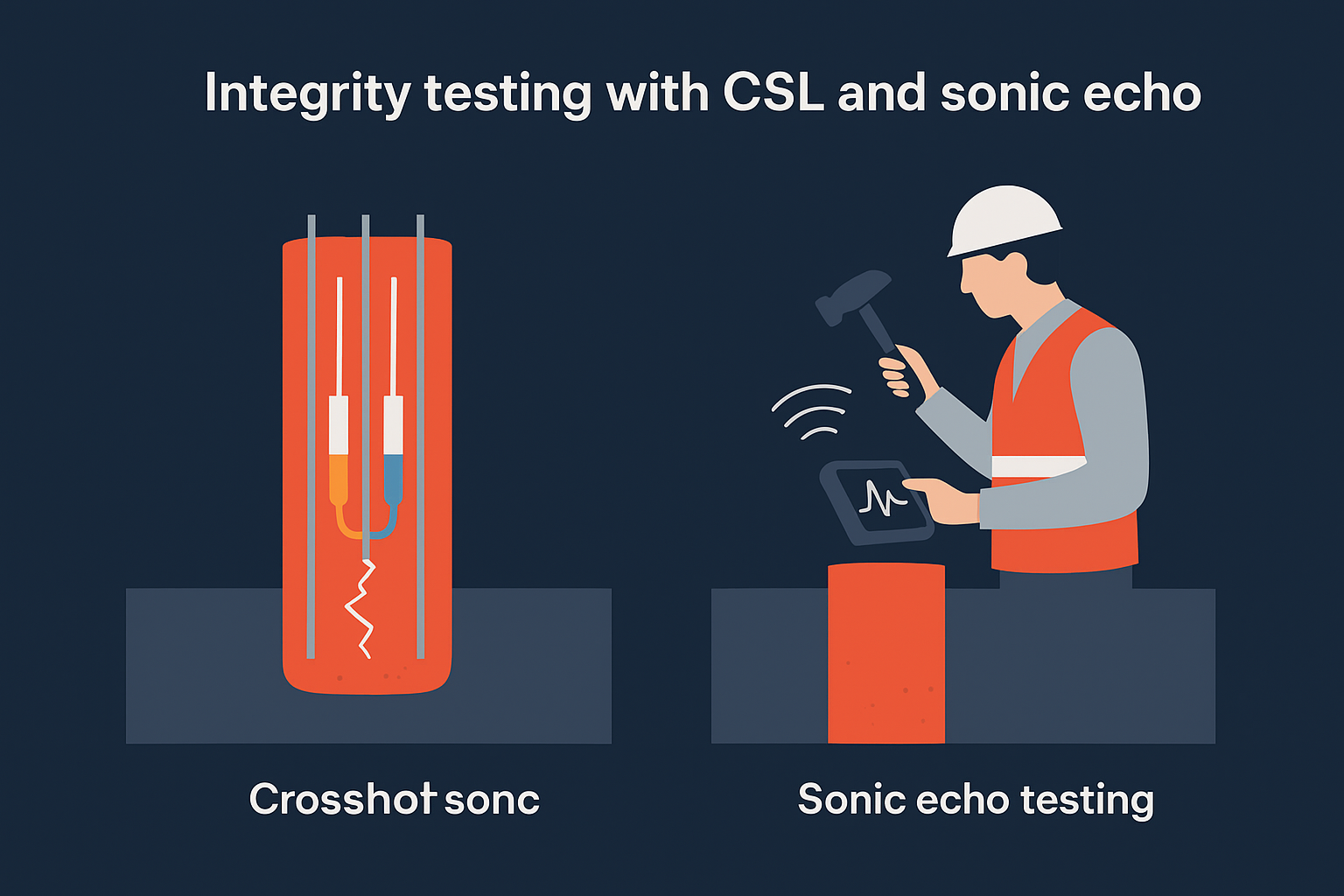
Integrity testing with CSL and sonic echo
Crosshole sonic logging (CSL) is the most common integrity test specified on bridge projects. Your crew installs steel access tubes inside the reinforcement cage before concrete placement, typically four tubes for shafts larger than 24 inches in diameter. After the concrete cures, a transmitter and receiver probe travel down adjacent tube pairs while emitting ultrasonic pulses. Anomalies in pulse velocity or amplitude flag zones where concrete is defective, segregated, or contaminated with slurry.
A CSL result showing a velocity drop greater than 20 percent below the baseline average in the same shaft requires engineering evaluation before you can accept that shaft for loading.
Sonic echo testing provides a faster, lower-cost alternative when access tubes are not installed. A handheld hammer strikes the shaft head while an accelerometer records the stress wave response. Your engineer reads the reflected waveform to identify major discontinuities or estimate shaft length. Sonic echo works best on shafts shorter than 30 feet and gives qualitative rather than quantitative results, so it supplements CSL rather than replacing it on critical bridge elements.
Load testing and acceptance criteria
Static load testing gives you the most direct confirmation that your shaft delivers the resistance your LRFD design assumed. A bi-directional load cell assembly placed at or near the shaft tip applies load hydraulically, pushing upward against side resistance and downward against end bearing simultaneously. This method eliminates the need for a reaction frame, which makes it practical on bridge sites with limited crane access.
Your acceptance criterion ties directly back to your AASHTO LRFD resistance factors: if you specified a higher factor based on a load test program, the test must confirm the predicted resistance or your shaft dimensions need revision. Collect deflection readings at multiple load increments and hold each increment until movement stabilizes before advancing to the next. Document full load-deflection curves so your engineer of record can verify that the shaft meets both strength and service limit state requirements before you move forward with bent cap construction.
Wrap-up and next steps
Drilled shafts for bridge foundations give your project capabilities that no other deep foundation system matches: concentrated load capacity, reliable seismic performance, and adaptability across difficult site conditions. Getting that performance requires aligning every phase, from your geotechnical investigation and LRFD resistance calculations through to construction sequencing and post-pour integrity testing. Skipping steps in any one phase introduces risk that compounds through every phase that follows.
The harder challenge is that a single bent can involve dozens of viable shaft configurations, each with a different cost, carbon footprint, and long-term durability profile. Evaluating that design space manually takes more time than most project schedules allow. Arched uses generative design and physics-driven simulation to run thousands of those combinations automatically and surface the candidates that best balance cost, constructability, and code compliance. If you want to see what that looks like on a real bridge project, explore the Arched platform and review what the tool delivers.