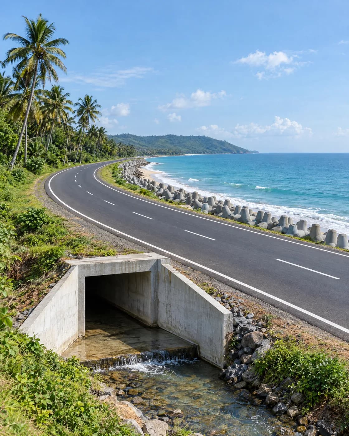
A bar bending schedule for a sloping bridge wing wall.
- Wall length
- 8.0 m
- Height segments
- 5
- Steel to cut
- 1.31 t
- Steel for payment
- 1.28 t
- Points to confirm
- 3
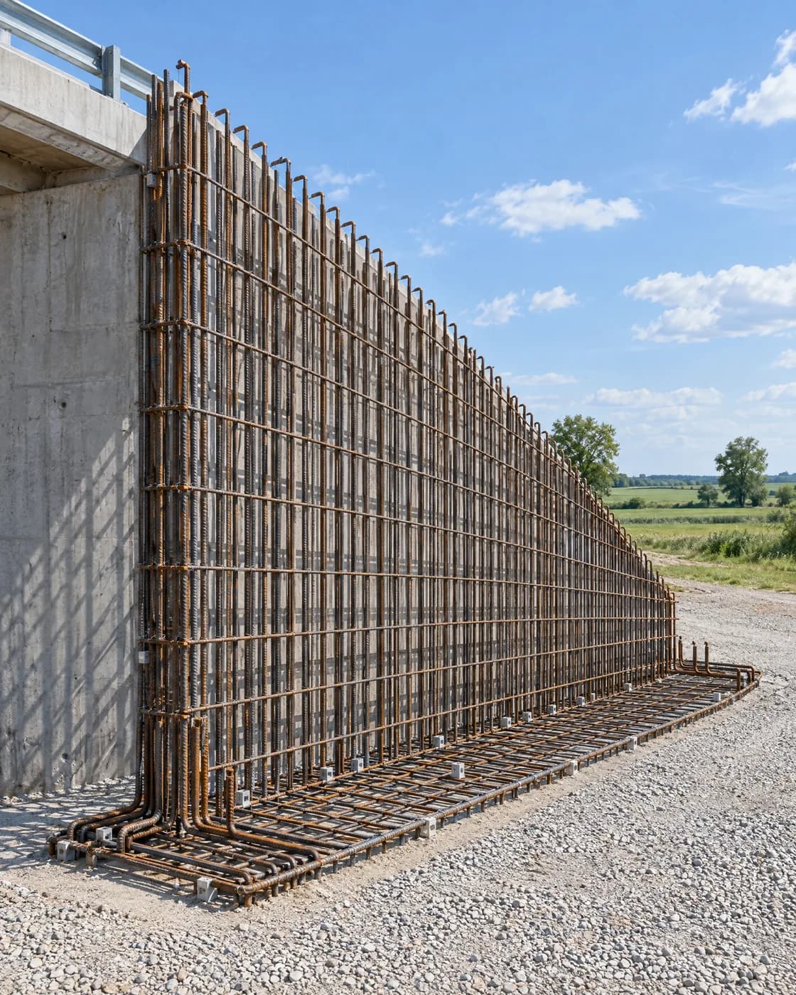
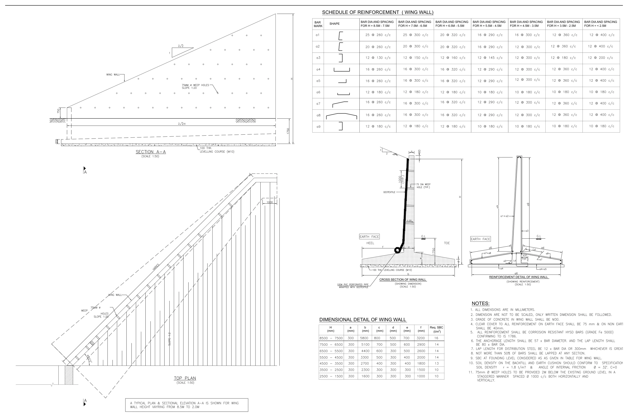
One typical drawing, and a wall that changes height.
The drawing gives one cross-section and two tables: the wall’s dimensions and its bars, each by band of height. A wall of one height reads straight off the tables. This one doesn’t, because its top slopes down along its length.
| Item | Basis |
|---|---|
| Wall | RCC cantilever wing wall at a bridge abutment, 8.0 m long |
| Height | 6.0 m at the abutment, falling to 2.0 m at the free end |
| Materials | M30 concrete, Fe 500D corrosion-resistant bars |
| Drawing | One typical section, a dimension table and a reinforcement schedule, both by height band |
| Standards | IS 2502 and SP 34 for bending and detailing, IS 1786 for bar mass, MoRTH Section 1600 for bending, splices and measurement |
- 01
Split the wall by height band
The drawing sizes the wall and its bars by bands of height. Because the top falls along the wall, it crosses five bands, so the schedule works in five segments.
- 02
Sized each segment
Base width, stem thickness, heel and toe for each segment, from the dimension table. That gives about 20 m³ of concrete.
- 03
Worked out every bar
Each bar mark's legs from the cover, the batter and the anchorage, with 2 bar diameters taken off for each 90° bend.
- 04
Followed the falling top
Stem bar lengths change at every bar position. Each is calculated, and the schedule gives the average with the shortest and longest, as SP 34 does.
- 05
Kept splices to a minimum
Distribution bars run full length along the wall. They are lapped only where the bar size changes, with laps staggered so no more than half fall at one section.
- 06
Checked the totals
The schedule total matches the summary, no bar is longer than 12 m stock, and steel works out at 65.7 kg/m³, inside the usual 60 to 90 for wing walls.
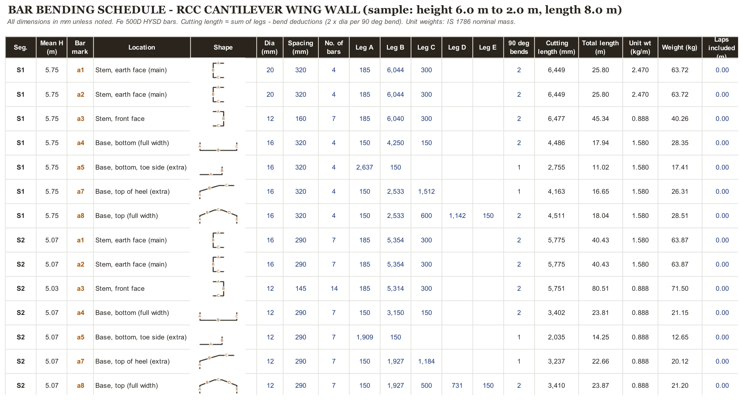
Every bar with its shape, legs and cutting length.
The bar yard cuts and bends from this sheet. Each row shows how its legs were worked out, and the workbook keeps them as live formulas, so a change to the drawing flows through.
| Bar | Weight | Share |
|---|---|---|
| 10 mm | 274 kg | 21% |
| 12 mm | 624 kg | 47% |
| 16 mm | 281 kg | 22% |
| 20 mm | 127 kg | 10% |
| Total | 1,306 kg | 100% |
What’s cut, and what’s paid.
The schedule weight, 1,306 kg, includes laps because the yard has to cut them. The measured weight, 1,283 kg, leaves laps out, as MoRTH 1608 measures it for payment. Wastage, chairs, spacers and binding wire are in neither; they sit in the rate.
Three things the drawing doesn’t say.
Where the drawing is silent, the schedule says what was assumed and what it does to the steel, so the designer can answer before the bars are cut.
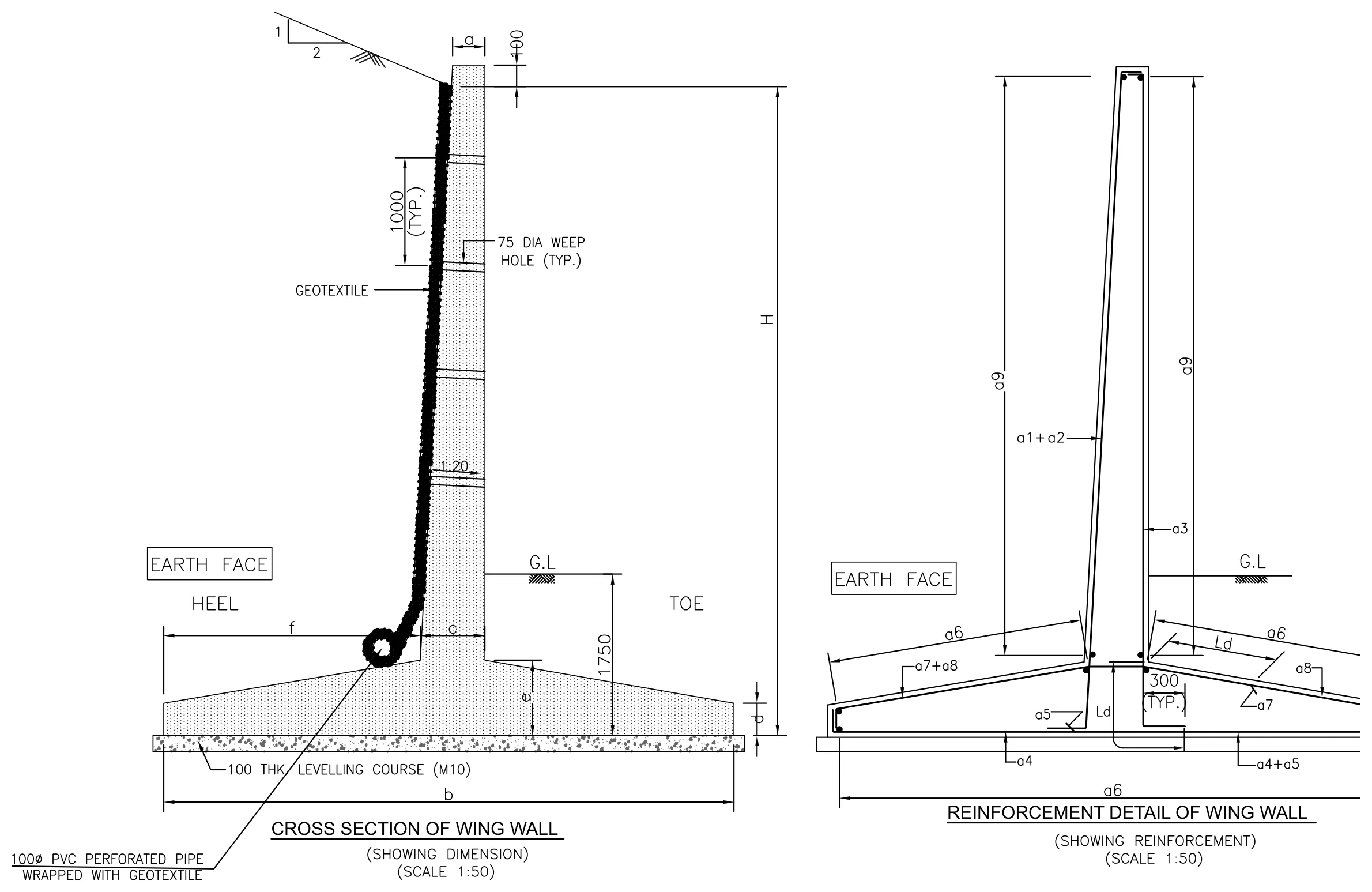
- 01Bar a2Drawn the same shape as a1, with no curtailment level shown. Taken full height. If it stops at mid-height, steel drops by about 7%.
- 02Stem topThe section shows the stem 400 mm above the height line. Bar lengths include it.
- 03Free endU-bars or end legs at the free end aren't detailed on the drawing, so they aren't included.
A sample prepared for a contractor from a typical drawing that carries no project particulars. The contractor is not named, and the figures are from the delivered workbook.