What Is The Finite Element Method? FEM And FEA Explained
Learn what is the finite element method and its role in structural analysis. Explore meshing, FEA workflows, and how to ensure model accuracy and safety.
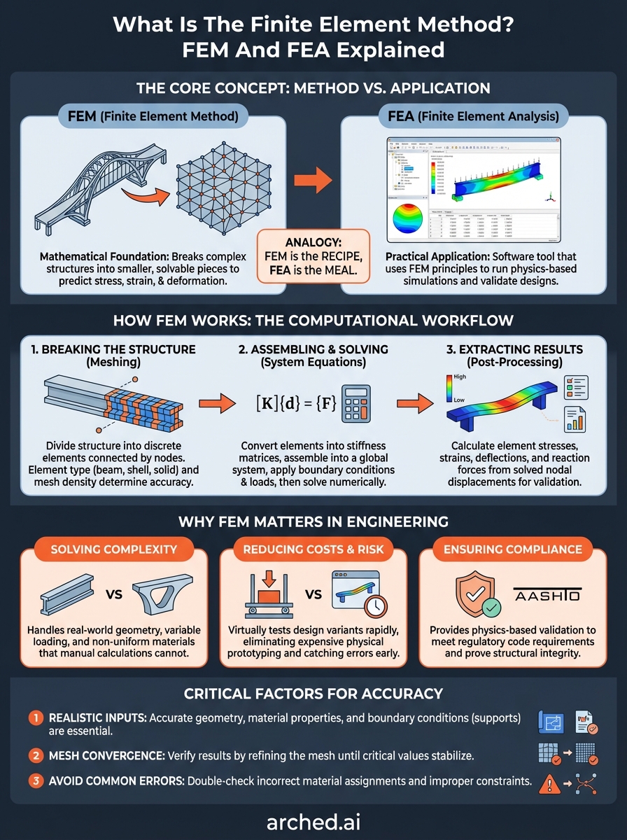
What Is The Finite Element Method? FEM And FEA Explained
Every bridge, beam, and structural component you design must withstand forces that can't always be calculated with simple hand equations. When geometry gets complex or loads vary across a structure, engineers turn to numerical methods. So what is the finite element method? It's the mathematical foundation that allows us to break down complex structures into smaller, solvable pieces, making accurate stress, strain, and deformation predictions possible.
FEM and its application, Finite Element Analysis (FEA), have become essential tools in structural engineering. Whether you're analyzing a girder under live load or evaluating a bridge deck configuration, FEA provides physics-based validation that manual calculations simply can't match at scale. Understanding how FEM works gives you insight into why simulation results behave the way they do, and how to interpret them correctly.
At Arched, we run thousands of FEM-driven simulations to find optimal bridge designs automatically, scoring each variant for cost, constructability, and code compliance. This article explains the fundamentals: what FEM is, how it relates to FEA, and how the method actually works to solve the structural problems you face on every project. By the end, you'll have a clear grasp of the numerical engine powering modern bridge design optimization.
Why FEM matters in engineering
You can't rely on hand calculations alone when designing modern infrastructure. Real-world structures rarely conform to the idealized cases you find in engineering textbooks, where uniform beams and simple support conditions dominate. Bridges experience variable loading patterns, temperature gradients, and complex contact interactions between components. FEM gives you the ability to model these conditions as they actually occur, capturing stress concentrations, deflection profiles, and failure modes that classical methods overlook.
Solving problems that closed-form equations can't handle
Most structural analysis textbooks teach you Euler-Bernoulli beam theory and moment distribution methods because they work for simplified cases. When you add curved geometry, non-uniform cross-sections, or multiple load paths, those approaches break down quickly. FEM discretizes your structure into finite elements, each governed by known mathematical relationships, then assembles them into a system you can solve numerically. This lets you analyze continuous bridge decks with variable thickness, girders with web openings, or pier caps with complex reinforcement patterns.
Consider a bridge girder with a tapered depth and variable web thickness. Hand calculations require you to make conservative assumptions that often lead to overdesign and wasted material. FEM captures the actual stress distribution along the entire member, identifying where you can reduce steel tonnage without compromising safety. The method handles material nonlinearity, contact between bearing pads and girders, and even time-dependent effects like creep and shrinkage.
"FEM transforms intractable structural problems into solvable numerical systems, giving you accurate predictions where closed-form solutions don't exist."
Reducing physical testing and prototyping costs
Physical load testing of full-scale bridges costs hundreds of thousands of dollars and requires weeks of preparation. You need instrumentation, calibrated load trucks, traffic control, and specialized personnel. FEM lets you run those same load cases virtually in hours instead of weeks, exploring multiple design variants before committing to fabrication. Every simulation you run eliminates guesswork and reduces the risk of field modifications.
Pre-construction validation through FEM also catches design errors early. When you discover a stress exceedance in simulation, you adjust the model and re-run the analysis immediately. Finding that same issue during construction means rework costs, schedule delays, and potential safety reviews. The method gives you confidence that your design performs as intended before steel gets cut or concrete gets poured.
Meeting regulatory and safety requirements
State DOTs and project owners increasingly require computational validation to supplement code-check calculations. AASHTO LRFD design specifications reference FEM-based approaches for complex structural systems where simplified methods don't apply. You need to demonstrate that your bridge meets strength and serviceability limits under all prescribed load combinations, and FEM provides the documented proof that regulators expect.
When you submit optimization proposals or value engineering alternatives, FEM results give reviewers quantifiable evidence that your changes maintain structural integrity. You're not asking them to trust intuition or rough estimates. Instead, you present stress plots, deflection profiles, and load path visualizations that prove compliance. This transparency speeds approval processes and builds trust with clients who need to justify design decisions to oversight committees.
FEM vs FEA and other numerical methods
You'll often see FEM and FEA used interchangeably, but they refer to different parts of the same process. Understanding what is the finite element method versus what FEA does helps you communicate more precisely with software vendors, review simulation reports critically, and know which technical concepts matter when evaluating results. Engineers also use other numerical methods to solve structural problems, and knowing when FEM outperforms alternatives saves you from applying the wrong tool to your bridge design challenges.
FEM is the method, FEA is the application
The Finite Element Method represents the underlying mathematical framework that discretizes continuous domains into finite elements. It defines how you approximate solutions to partial differential equations governing stress, strain, and displacement. FEA, on the other hand, is the practical implementation of FEM through software packages like ANSYS, Abaqus, or SAP2000. When you run a bridge analysis in these programs, you're applying FEM principles through a graphical interface that handles the matrix operations behind the scenes.
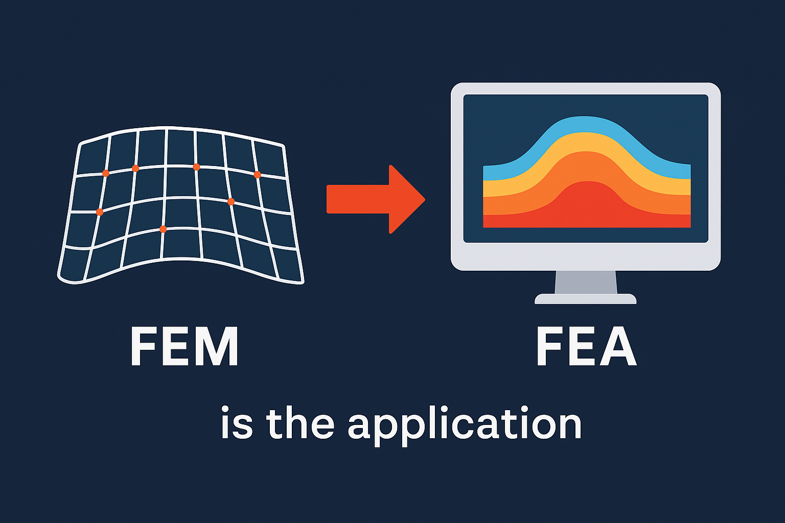
Think of FEM as the recipe and FEA as the meal you prepare from it. You don't need to derive stiffness matrices by hand to run simulations, but understanding the FEM recipe helps you interpret why certain mesh patterns produce better results or why convergence failures occur. FEA gives you answers, but FEM explains why those answers are trustworthy.
"FEM provides the theoretical foundation; FEA delivers the simulation results you use to validate bridge designs."
How FEM compares to other numerical approaches
Finite Difference Method (FDM) solves equations by approximating derivatives at grid points, making it simpler to implement but less flexible with complex geometries. You'll find FDM used more often in fluid dynamics and heat transfer than in structural analysis because it struggles with irregular boundaries like curved bridge decks or skewed pier caps.
Boundary Element Method (BEM) only discretizes the surface of a structure rather than its entire volume, reducing computational cost for certain problems. BEM works well for infinite domain problems like soil-structure interaction, but FEM remains the standard for bridge analysis because you need to know internal stresses throughout the entire cross-section, not just at boundaries.
Meshless methods avoid creating elements altogether, using scattered nodes instead. These approaches show promise for fracture mechanics and large deformation analysis, but they lack the mature software ecosystem and code acceptance that FEM-based FEA tools provide for everyday bridge design work.
How FEM works step by step
Understanding what is the finite element method requires walking through the computational workflow that transforms your bridge geometry into actionable stress and deflection data. The process follows a logical sequence that every FEA software package executes, whether you're analyzing a simple beam or a complete bridge system. Each step builds on the previous one, converting your design geometry into a mathematical model, solving it numerically, and presenting results you can validate against code requirements.
Breaking your structure into finite elements
You start by dividing your continuous bridge structure into discrete elements, a process called meshing. Each element represents a small portion of your girder, deck, or pier, connected to neighboring elements at shared nodes. The software assigns material properties, cross-section dimensions, and element types (beam, shell, solid) based on the structural components you're modeling. A finer mesh with more elements captures stress gradients more accurately but requires longer solve times.
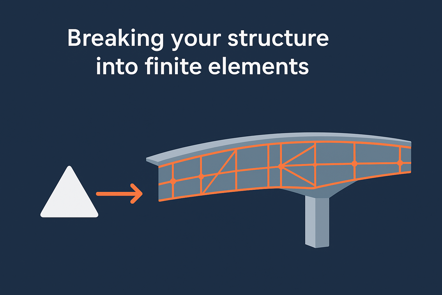
Element selection matters because different shapes handle different behaviors. Shell elements work well for thin bridge decks, while solid elements better capture stress concentrations at bearing locations. You control mesh density in regions where you expect high stress variation, like around web openings or at support locations, while using coarser meshes in areas with uniform stress fields.
"Mesh quality directly determines how accurately your simulation captures the real structural behavior of your bridge components."
Assembling and solving the system equations
FEM converts each element into a stiffness matrix that relates nodal displacements to applied forces through the material's constitutive laws. The software assembles these individual matrices into a global system of equations representing your entire structure. You then apply boundary conditions that constrain displacements at supports and specify loads at their actual locations. This creates a system of linear equations that the solver processes using numerical algorithms like direct factorization or iterative methods.
The solver computes displacement values at every node that satisfy equilibrium equations and compatibility conditions simultaneously. Large bridge models can involve millions of degrees of freedom, requiring efficient matrix storage and solution strategies. Modern solvers handle this automatically, but you control convergence tolerances that determine solution accuracy.
Extracting results you can use
Once the solver finds displacement solutions, the software back-calculates element stresses and strains using the computed nodal displacements. You extract reaction forces at supports, deflections at midspan, and stress components throughout your structure. Post-processing tools display these results as contour plots, deformed shapes, and numerical tables that you compare against AASHTO limits and project specifications.
Core building blocks of a good FEM model
You need more than software proficiency to build FEM models that produce trustworthy results. The accuracy of your bridge analysis depends on how well your model represents the actual structure, not just on computational power. When you understand what is the finite element method at its core, you realize that garbage inputs always produce garbage outputs regardless of solver sophistication. Three fundamental building blocks determine whether your simulation captures real structural behavior or generates misleading stress predictions that could compromise safety.
Geometry and material properties that match reality
Your model's geometry must reflect as-built dimensions with tolerances that matter for structural response. A girder depth error of half an inch might seem trivial, but it changes section properties enough to alter stress distributions by five percent or more. You input accurate material properties including elastic modulus, Poisson's ratio, yield strength, and density values that match material certifications. Bridge steel grades vary, and using generic properties instead of mill test reports introduces unnecessary uncertainty.
Temperature-dependent material behavior matters for bridges exposed to seasonal extremes. Concrete modulus decreases at elevated temperatures, while steel thermal expansion affects bearing movements and connection forces. You account for these variations when they influence critical design checks.
Boundary conditions that represent actual supports
Support conditions control how your structure distributes loads, making them the most critical inputs after geometry. You model pinned supports at piers with translational restraints in all directions but rotational freedom about the bearing axis. Roller supports at expansion bearings allow longitudinal movement while restraining vertical and transverse displacement. Fixed supports at abutments prevent all six degrees of freedom at those nodes.
"Incorrect boundary conditions produce plausible-looking results that completely misrepresent how your bridge actually behaves under load."
Contact interactions between bearing pads and girder flanges require nonlinear contact elements rather than simple constraints. Soil-structure interaction at foundations needs spring stiffnesses derived from geotechnical reports, not assumed rigid supports.
Element selection and mesh refinement strategy
You choose element types based on structural behavior you need to capture. Beam elements work for girder analysis when you care about section forces, while shell elements model deck behavior including out-of-plane bending. Solid elements capture three-dimensional stress states at bearing locations or connection details where simplified elements miss critical stress concentrations.
Mesh refinement follows stress gradients, not arbitrary patterns. You place finer meshes near load application points, geometric discontinuities, and regions where code checks govern. Uniform fine meshes waste computational resources without improving accuracy in low-stress zones.
Accuracy, convergence, and common mistakes
You can't assume your FEM results are correct just because the software produces colorful stress plots and reasonable-looking numbers. Understanding what is the finite element method requires recognizing that numerical approximation errors exist in every simulation, and you need systematic approaches to verify your results before using them for design decisions. Convergence testing, accuracy validation, and awareness of common modeling pitfalls separate reliable analyses from simulations that produce dangerously misleading outputs.
Testing mesh convergence before trusting results
You verify solution accuracy by running the same model with progressively finer meshes and comparing results at critical locations. When maximum stress changes less than two percent between successive mesh refinements, you've achieved mesh convergence for that response quantity. Without this verification step, you don't know whether your reported stress of 35 ksi represents the true value or whether a finer mesh would reveal 42 ksi that exceeds your allowable limit.
Convergence testing focuses on the structural responses that control your design checks, not arbitrary metrics. You track maximum girder stress, midspan deflection, and bearing reactions through successive mesh refinements. Local stress concentrations converge more slowly than global quantities like support reactions, requiring denser meshes in those regions.
"Mesh convergence testing proves your simulation captures actual structural behavior rather than numerical artifacts from coarse discretization."
Avoiding material and constraint errors
The most frequent modeling mistakes involve incorrect material assignments and boundary condition errors that experienced engineers still make under deadline pressure. You double-check that concrete deck elements use concrete properties rather than steel values carried over from previous models. Support nodes must constrain the correct degrees of freedom, because releasing vertical restraint at a pier support produces catastrophic instability that doesn't reflect physical reality.
Load application errors introduce significant inaccuracies when you apply distributed loads as point forces without proper tributary area calculations. Temperature gradient loads require careful application across deck thickness, not as uniform temperature changes that miss thermal stress distributions entirely. You validate total applied load against hand calculations before running the analysis, catching input errors that produce results an order of magnitude different from expected values.
Next steps
You now understand what is the finite element method and how it powers the structural analysis behind every bridge design validation. The concepts covered here form the technical foundation you need to interpret FEA results critically, catch modeling errors before they compromise safety, and communicate simulation findings to clients who demand documented proof of code compliance.
Arched automates this entire FEM workflow at scale, running thousands of physics-driven simulations to optimize your bridge designs for cost, constructability, and carbon impact. Instead of manually iterating through design alternatives, you upload plan sets and receive optimization reports that quantify exactly which configurations deliver the best value. Our platform handles mesh generation, convergence testing, and AASHTO code checks automatically, giving you validated design variants ready for professional review. Explore how Arched transforms bridge optimization from weeks of manual FEM work into automated analysis that finds the single best solution among 10,000 possibilities.